
Flux Core Welding Settings and Wire Chart
Flux core welding settings explained: wire diameter, voltage and wire feed, stickout and polarity, plus how to build your own settings chart from test beads.

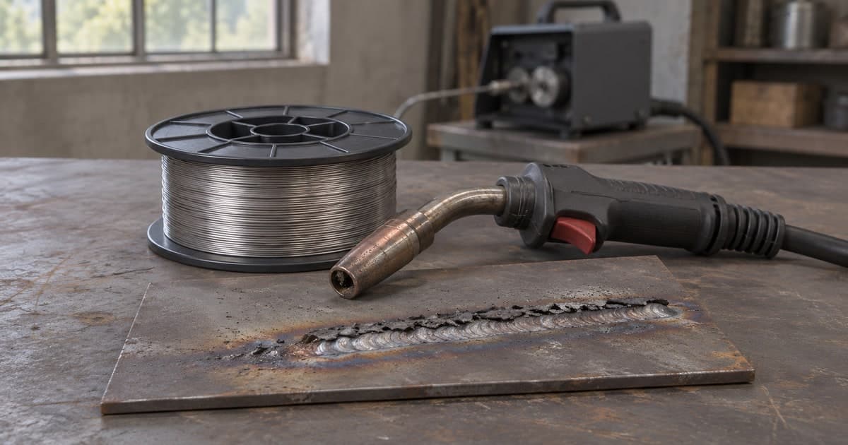
Flux core welding settings are harder to copy from a table than many welders expect. Two wires with the same diameter can run differently, and the same wire can behave differently on a thin plate and a thick joint. A chart is useful, but only when you know which variable it is describing and which one you still have to adjust by hand.
This guide explains the settings that matter, how they affect the weld, and how to build a reliable chart for your own machine and wire. It does not give a single universal voltage and wire speed, because the right figures depend on the electrode data sheet and the power source you use.
Two Flux Core Processes, Two Sets of Rules
Flux core arc welding (FCAW) is not one process. The original wires needed a shielding gas, usually carbon dioxide, and that type is now called FCAW-G, or gas-shielded. Self-shielded wires, FCAW-S, carry their own protection in the flux and need no external gas.
The distinction changes the settings. Gas-shielded wire is often run in the shop with a cylinder, and it suits indoor work. Self-shielded wire is widely used outdoors, where wind would blow away a gas shield. Always read the data sheet for the exact wire you have, because it sets the polarity, the gas and the voltage range for that electrode.
For background on the process itself, what is flux cored welding covers how the flux core works and where the process is used. If you are weighing it against solid wire, flux cored vs MIG welding compares the two directly.
Wire Diameter
Flux cored wire is available in a range of diameters, commonly from about 0.035 inch up to 0.125 inch. The size you choose changes what the wire can do. Larger diameters carry more current and deposit weld metal faster, which suits thick sections. Smaller diameters suit thinner material and welding out of position, such as vertical or overhead work.
Start with the wire diameter, because it limits the output range you can use. A wire that is too large for the thickness can overheat the joint and cause burn-through, while a wire that is too small may not fuse thick material even at high settings.
Voltage and Wire Feed Speed
On a constant-voltage machine, the wire feed speed sets the welding current. Voltage sets the arc length and the shape of the bead. Raising the wire feed speed increases current and heat, and raising voltage lengthens the arc and flattens the bead. The two settings work together, so you should adjust them as a pair rather than one at a time.
A good starting point is the range printed on the wire data sheet or the machine's own recommendation. Treat it as a range to test within, not a fixed number. Make test beads on scrap of the same material and thickness, and adjust in small steps until the arc sounds steady and the bead wets in evenly at the edges.
Watch for the signs of a setting that is off. A bead that is too high and narrow with little penetration usually needs more voltage or current. A bead that is wide and flat with heavy spatter often has too much voltage for the wire speed, so reduce voltage first.
Electrical Stickout
Electrical stickout is the length of wire between the contact tip and the end of the electrode. It matters more on flux core than many welders realise. Stickout changes the shielding, the current and the arc stability.
The reason is resistive heating in the wire. The longer the wire extension, the more electrical energy is spent heating the wire itself, and the less reaches the arc. A gun held further from the work therefore needs more wire speed to deliver the same current, and the arc can become less stable.
Keep the stickout consistent during a pass, and check the manufacturer's recommended range for your wire. Changing stickout mid-bead is a common cause of uneven penetration.
Polarity
Polarity is the direction current flows between the electrode and the work. Many flux cored wires run on one polarity, and some run on the other, so the data sheet is the authority. As a general pattern, self-shielded wires are often run with the electrode negative (DCEN), while gas-shielded wires are often run with the electrode positive (DCEP).
Setting the wrong polarity can produce a rough arc, poor penetration and excessive spatter, which looks like a settings problem but is not. If a wire behaves badly even though the voltage and wire speed look right, check the polarity connection before changing anything else.
Gas Choice for Gas-Shielded Wire
For gas-shielded flux cored wire, the gas is part of the settings. The data sheet names the gas and often a flow rate, and using a different gas can change the penetration profile and the spatter level. Carbon dioxide and argon-based mixes behave differently, so do not swap them without checking the wire data.
Self-shielded wire needs no external gas. Do not add a cylinder to a self-shielded setup, because the gas does not help and can disturb the shielding that the wire relies on.
Building Your Own Settings Chart
A chart you trust is one you have made yourself. Use the same wire, machine and gun for every test, and record the variables as you go. A simple record is enough:
- Wire diameter and brand, plus the polarity and gas used
- Voltage and wire feed speed, as shown on the machine
- Stickout measured from the contact tip
- Material thickness and joint type
- A note on the bead: penetration, width, spatter and slag removal
Make a short bead at a few settings across the range, cut or break the test piece, and check the penetration. Keep the settings that give sound fusion and an even bead, and write them down against the thickness. Over time, that record becomes a chart that matches your machine, which is more useful than any generic table.
Keep the chart near the machine and add a note when you change wire or gun. A new wire batch or a different tip can shift the result, and a chart that is not updated will mislead you.
Keeping Settings Consistent From Job to Job
Settings drift for ordinary reasons. A new spool of wire may come from a different batch, a contact tip wears and changes the electrical contact, and a liner that is partly blocked changes how smoothly the wire feeds. Each of those can shift the arc enough to make a good setting feel wrong, even though nothing on the machine has changed.
When a weld suddenly looks different, check the consumables before you change the numbers. Look at the contact tip for wear, check that the wire feeds straight and smoothly, and confirm the stickout. Only then adjust voltage and wire speed in small steps. Changing several things at once makes it impossible to know which one fixed the problem.
Keep a short note with each spool or wire batch, recording the settings that worked. When you open a new spool, run a test bead before the real part. That habit costs a few minutes and avoids spoiling a finished joint.
Slag and Cleaning
Flux cored welds produce slag, which must be removed between passes and before inspection. Leaving slag in place can trap it inside the weld as a slag inclusion, which is a defect. Chip and brush the slag clean before you lay the next pass, and check the bead visually after each one.
Fume is significant with this process. Good ventilation matters, especially with self-shielded wire, which produces large amounts of fume. Keep your head out of the plume and follow the safety data for the wire.
Common Problems and Likely Causes
Excessive spatter. Check the voltage and wire speed balance, the polarity and the gas, if you are using gas-shielded wire. Too much voltage for the wire speed is a frequent cause.
Poor penetration. Increase current through wire speed, check that the wire diameter suits the thickness, and keep the stickout consistent.
Slag inclusions. Remove slag fully between passes. Improper cleaning is the usual cause, not the wire itself. Defects of this kind are listed alongside other weld problems in the stick welding defects guide, which is useful for comparing causes across processes.
Burn-through on thin plate. Reduce wire speed, move to a smaller diameter, and keep the travel speed steady.
Porosity on gas-shielded wire. Check the gas flow, the cylinder, the regulator and any draught in the work area. Self-shielded wire does not need external gas, but it still needs the correct stickout.
Safety Basics
Flux cored welding produces significant fume and slag, so ventilation is essential. Use local extraction where you can, or work in an area with good airflow. Wear a helmet with the correct shade and cover exposed skin, because the arc is intense.
Check the cylinder, regulator and hoses before each session if you use gas-shielded wire. Keep the cylinder secured, and do not weld near flammable material. Sparks and slag can start fires.
Putting It Together
Set up flux core welding from the wire data sheet, not from memory. Choose the diameter for the thickness, set voltage and wire speed as a pair, hold the stickout steady, and confirm the polarity and gas before you blame the machine.
Then build your own chart from test beads on scrap. That record, kept with the machine and updated when the wire or gun changes, will serve you better than any general table.
Frequently asked questions
What is the difference between FCAW-G and FCAW-S?
FCAW-G is gas-shielded flux cored welding and needs an external shielding gas. FCAW-S is self-shielded and carries its own protection in the flux, which makes it practical outdoors.
How do I set voltage and wire feed speed for flux core?
Start from the range on the wire data sheet or the machine's recommendation. Adjust voltage and wire speed together in small steps, using test beads on scrap of the same thickness. The MIG welding wire speed voltage chart follows the same logic for solid wire and is a useful comparison while you learn how the two settings interact.
Why does stickout matter in flux core welding?
Stickout changes the current and the arc stability, because the wire extension heats resistively. Keep the stickout consistent during a pass and within the wire manufacturer's range.
Which polarity should I use for flux core wire?
Check the wire data sheet, because polarity depends on the electrode. Self-shielded wire is often run with the electrode negative, while gas-shielded wire is often run with the electrode positive.
What wire diameter should I choose?
Larger diameters carry more current and suit thick sections. Smaller diameters suit thin material and out-of-position work. Match the diameter to the thickness and the position you need.
Why does my flux core weld have lots of spatter?
Spatter is often caused by too much voltage for the wire speed, or by the wrong polarity or gas. Check those settings before adjusting anything else.
Do I need to clean slag between passes?
Yes. Slag must be removed between passes and before inspection, because trapped slag can form inclusions inside the weld.
Is flux core fume dangerous?
Flux core produces significant fume, especially with self-shielded wire. Use good ventilation or local extraction, keep your head out of the plume, and follow the safety data for the wire.
References
- Cameron Kjeldgaard, History of FCAW - Welding Theory Fundamentals, OpenWA, accessed 2026-11-16.
- Gas Metal Arc Welding - Advanced High Strength Steel (AHSS) Guidelines, accessed 2026-11-16. Used for the principle of resistive heating in the electrode extension; this page covers GMAW, not FCAW.
- Weldik, Flux Core Welding - FCAW Setup, Wire & Settings - Weldik (supplier), accessed 2026-11-16. Supplier source, used only for the polarity pattern for self-shielded and gas-shielded wire; check your wire data sheet.