
MIG Welding Wire Speed and Voltage Chart Guide
A practical MIG welding wire speed and voltage chart for steel, aluminum, and flux-core wire, with tuning tips and a troubleshooting guide.

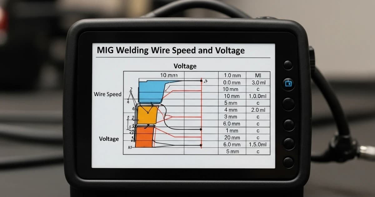
Every MIG welder eventually asks the same question: what wire speed and voltage should I actually be running? A MIG welding wire speed and voltage chart answers that question fast, giving you a starting point based on wire diameter and material thickness instead of guessing and burning through scrap metal. But a chart alone only gets you close. The real skill is understanding why those numbers work, so you can adjust them the moment your material, gas, or position changes.
This guide breaks down the numbers, explains the relationship between wire feed speed and voltage, and walks through the adjustments that separate a chart-perfect setting from a genuinely good weld.
How Wire Feed Speed and Voltage Work Together
In gas metal arc welding (GMAW), wire feed speed (WFS) and voltage are not independent dials you set once and forget. They work as a pair, and each one does a different job.
Wire feed speed controls amperage. Faster wire feed pushes more filler metal into the arc, which draws more current from the power source. More amperage means more heat, deeper penetration, and a faster deposition rate. This is why wire feed speed and amperage are often treated as the same setting on a MIG machine.
Voltage controls arc length and bead shape. Higher voltage stretches the arc out, producing a flatter, wider bead with a smoother transition into the base metal. Lower voltage shortens the arc, giving a narrower, more convex bead. Voltage that doesn't match the wire speed is one of the most common reasons welds look wrong even when the amperage seems correct.
The two settings have to stay in balance. Wire feed speed that's too fast for the voltage causes the wire to stub into the puddle. Voltage that's too high for the wire speed produces a wide, flat, "washy" bead with almost no penetration. A good chart gives you a matched pair instead of two numbers picked in isolation.
The "One Amp Per Thousandth" Rule of Thumb
A commonly used shortcut for estimating amperage from material thickness is the one amp per thousandth rule: multiply the material thickness in thousandths of an inch by roughly one amp. A 1/8-inch (0.125 in, or 125 thousandths) piece of steel needs somewhere around 125 amps as a starting point. This rule holds reasonably well between about 50 and 250 amps, which covers the vast majority of MIG welding done in fabrication shops, farm shops, and home garages.
Once you know the target amperage, you can convert it to wire feed speed using an approximate ratio for each wire diameter:
| Wire diameter | Approx. amperage range | IPM per amp (approx.) |
|---|---|---|
| 0.023 in (0.6 mm) | 30–130 A | 3.5 |
| 0.030 in (0.8 mm) | 40–145 A | 2.0 |
| 0.035 in (0.9 mm) | 50–180 A | 1.6 |
| 0.045 in (1.2 mm) | 75–250 A | 1.0 |
So for that 1/8-inch steel example at roughly 125 amps using 0.035-inch wire, you'd expect a wire feed speed near 125 × 1.6 ≈ 200 inches per minute (IPM). This is useful for building intuition, but it is a rough approximation, not a substitute for reading the actual weld.
MIG Welding Wire Speed and Voltage Chart for Mild Steel
The table below gives practical starting-point settings for solid ER70S-6 wire on mild steel, using a 75% argon / 25% CO2 shielding gas mix, flat position, with a standard contact-tip-to-work distance of around 3/8 to 1/2 inch. Treat every value as a range to dial in, not an exact target.
| Material thickness | Wire diameter | Voltage | Wire feed speed | Approx. amperage |
|---|---|---|---|---|
| 24 ga (0.6 mm) | 0.023 in | 15–16 V | 70–100 IPM | 30–45 A |
| 20 ga (0.9 mm) | 0.023–0.030 in | 16–17 V | 100–150 IPM | 45–65 A |
| 18 ga (1.2 mm) | 0.030 in | 17–18 V | 150–220 IPM | 65–90 A |
| 16 ga (1.6 mm) | 0.030 in | 18–19 V | 220–280 IPM | 90–120 A |
| 1/8 in (3.2 mm) | 0.030–0.035 in | 18–20 V | 280–350 IPM | 120–150 A |
| 3/16 in (4.8 mm) | 0.035 in | 19–21 V | 300–380 IPM | 150–180 A |
| 1/4 in (6.4 mm) | 0.035–0.045 in | 21–23 V | 350–450 IPM | 180–225 A |
| 3/8 in (9.5 mm)+ | 0.045 in | 23–26 V | 400–500 IPM | 225–280 A |
Below roughly 1/8 inch of steel, you'll almost always be in short-circuit transfer, where the wire physically touches the puddle and shorts out 90 to 200 times per second. Above about 1/4 inch with the right gas and higher voltage, the process can transition into spray transfer, which deposits metal faster and cleaner but generates more heat and only works well in flat and horizontal positions.
How to Read and Use This Chart
Start by matching your material thickness to the closest row, then set your machine to the low end of the range if you're welding out of position, on a fit-up with a gap, or worried about burn-through. Move toward the high end for flat, tight-fitting joints where you want faster travel and full penetration.
Run a test bead on scrap of the same thickness before touching the actual workpiece. Chart values assume clean metal, a properly sized contact tip, correct polarity, and good ground connection — any one of those being off will shift the numbers you actually need.
Wire Feed Speed and Voltage for Flux-Cored Wire (FCAW)
Flux-cored settings are not interchangeable with solid-wire MIG settings, even at the same wire diameter. Self-shielded flux-cored wire (FCAW-S, such as E71T-11) runs on DCEN (electrode negative) polarity, the opposite of the DCEP polarity used for solid wire with shielding gas, and it needs a longer stickout — typically 1/2 to 3/4 inch, roughly double what solid wire wants — to let the flux core burn cleanly and generate its own shielding gas.
| Material thickness | Wire diameter | Voltage | Wire feed speed |
|---|---|---|---|
| 18–16 ga (1.2–1.6 mm) | 0.030 in | 17–18 V | 180–230 IPM |
| 3/16 in (4.8 mm) | 0.035 in | 18–20 V | 230–280 IPM |
| 1/4 in (6.4 mm) | 0.035–0.045 in | 19–21 V | 250–320 IPM |
| 3/8 in (9.5 mm)+ | 0.045 in | 21–24 V | 300–380 IPM |
Flux-cored parameters are more sensitive to stickout than solid wire. A quarter-inch change in gun distance from the joint can shift effective amperage by 20 amps or more, so consistent gun handling matters more here than with gas-shielded solid wire. This sensitivity, combined with the process's tolerance for wind and rust, is exactly why self-shielded flux-core is popular for outdoor and field work where gas shielding isn't practical.
MIG Welding Settings for Aluminum
Aluminum settings look nothing like steel settings at the same thickness, and that surprises a lot of welders coming from steel. Aluminum conducts heat away from the weld pool much faster than steel, so it needs significantly more wire speed and heat to get a proper puddle going, even though it melts at a lower temperature.
| Material thickness | Wire diameter | Voltage | Wire feed speed |
|---|---|---|---|
| 1/16 in (1.6 mm) | 0.030 in | 17–19 V | 250–320 IPM |
| 1/8 in (3.2 mm) | 0.035 in | 21–23 V | 450–600 IPM |
| 3/16 in (4.8 mm) | 0.035–3/64 in | 22–24 V | 500–600 IPM |
| 1/4 in (6.4 mm)+ | 3/64–1/16 in | 24–26 V | 550–650+ IPM |
Aluminum should be shielded with 100% argon, never a CO2 blend, or the weld pool will oxidize and the arc will become unstable. Because aluminum wire is soft and easily deforms in a standard drive system, feeding it any real distance through a regular gun liner tends to cause birdnesting and feed problems. A spool gun or push-pull feed system is strongly recommended for anything beyond short, occasional aluminum welds. Many welders also move to pulsed MIG for aluminum once material gets into the 1/8-inch-plus range, since pulsing controls heat input more precisely than a straight constant-voltage arc.
What Actually Changes Your Settings
A chart gives you a baseline for one specific combination of wire, gas, position, and joint. Change any of those variables and the "correct" voltage or wire speed moves with it.
Shielding Gas and Voltage
Gas composition has a direct effect on arc voltage, independent of wire speed. A 100% argon shield produces a soft, low-voltage arc, and on steel it tends to run cold and unstable with tall, ropey beads — argon alone works for aluminum and some non-ferrous metals, but not for bare steel. Adding CO2 to the mix raises the arc voltage needed for a stable arc because CO2 is less easily ionized and has higher thermal conductivity than argon, which is also why CO2 additions improve penetration. A 75/25 argon/CO2 blend is the most common choice for steel because it balances arc stability and low spatter (from the argon) with solid penetration (from the CO2). Straight CO2 gives the deepest penetration and the fastest travel speeds but comes with a harsher, less stable arc and noticeably more spatter — it typically needs a few extra volts compared to a 75/25 blend at the same wire speed.
Contact-Tip-to-Work Distance: The Most Overlooked Detail
Most beginners fixate on the voltage and wire speed dials and ignore gun position, but contact-tip-to-work distance (CTWD, sometimes called stickout) changes your actual welding amperage even when the machine's dial hasn't moved. Extending the stickout adds electrical resistance in the wire between the contact tip and the arc, which lowers the current for a given wire feed speed; shortening it does the opposite. In practical terms, moving the gun from around 5/8 inch to 1 inch of stickout can swing effective amperage by 60 to 70 amps on some setups — enough to take a properly dialed-in weld and turn it into a cold, poorly fused one without touching a single control.
For short-circuit MIG welding, keep stickout to roughly 1/4 to 3/8 inch. Watching this distance consistently is often the difference between a welder who fights their machine and one who gets repeatable results from the same chart settings every time.
Position and Joint Design
Out-of-position welding — vertical, overhead, or horizontal fillets — generally calls for settings toward the lower end of the chart range, since a smaller, faster-freezing puddle is easier to control against gravity. Root gaps, poor fit-up, and thin material near thick material also push you toward lower heat, while deep-groove joints or thick, tight-fitting sections favor the higher end of the range for adequate fusion.
Reading the Arc: How to Fine-Tune Beyond the Chart
Once you're in the right neighborhood, the fastest way to dial in exact settings is to listen and look, not just read a dial. A properly matched wire speed and voltage produces a steady, consistent crackle often described as bacon frying in a pan — a tight, even sizzle rather than a series of individual pops or a smooth hiss.
A few reliable signs to watch for on a test bead:
- Steady, even sound with light spatter: settings are close to correct.
- Loud popping or the gun pushing back at you: wire speed is too fast for the voltage, or voltage is too low — the wire is stubbing into the puddle faster than the arc can melt it off.
- Arc that flickers, wanders, or feels weak with a hissing sound and large, erratic spatter: wire speed is too slow for the voltage, producing globular transfer instead of a controlled short-circuit or spray arc.
- Flat, wide, wet-looking bead with almost no buildup: voltage is too high relative to wire speed.
- Narrow, tall, rope-like bead sitting on top of the metal: voltage is too low relative to wire speed, and penetration is likely poor.
Make small adjustments — a volt at a time, and a modest step in wire speed — rather than large swings, and re-test after each change. This is also where a chart's limits show up clearly: two machines from different manufacturers, two spools of wire from different brands, or even a new roll of the same wire can all shift the "correct" number by a volt or two.
Common Wire Speed and Voltage Mistakes
Most bad MIG welds trace back to one of a handful of repeatable mistakes, almost all involving a mismatch between wire speed and voltage rather than either setting being wrong in isolation.
Wire stubbing and birdnesting. When wire feed speed outruns the voltage's ability to melt it, the wire jams into the puddle, pushes the gun back, and can pile up in the drive rolls, forming a birdnest. The fix is almost always to raise the voltage slightly rather than cut the wire speed, unless the wire speed itself is clearly excessive for the material.
Excessive spatter. This shows up when voltage is too low for the wire speed being used, or occasionally when it's too high and the arc turns globular. Small, incremental voltage adjustments in either direction, guided by the sound of the arc, usually resolve it faster than guessing.
Cold welds with poor fusion. A bead that looks like a bead of caulk sitting on top of the metal rather than blending into it is a sign of too little heat — both voltage and wire speed need to come up together, not just one of them.
Burn-through on thin material. The opposite problem: too much heat for the thickness of metal being welded. Drop both wire speed and voltage, and consider a smaller-diameter wire if you're pushing the low end of your current wire's range.
Troubleshooting Table
| Symptom | Likely cause | Fix |
|---|---|---|
| Wire stubs or pushes gun away | WFS too high for voltage | Raise voltage slightly, or reduce WFS |
| Heavy, erratic spatter | Voltage too low for WFS | Raise voltage in small steps |
| Flat, wide, "washy" bead with no buildup | Voltage too high for WFS | Lower voltage or raise WFS |
| Narrow, tall, rope-like bead | Voltage too low for WFS | Raise voltage |
| Weak penetration, cold lap | Overall heat too low | Increase both voltage and WFS together |
| Burn-through on thin metal | Overall heat too high | Decrease both voltage and WFS, consider smaller wire |
| Arc wanders, inconsistent amperage | CTWD (stickout) inconsistent | Hold a steady 1/4–3/8 in stickout |
| Popping sound with large droplets | Globular transfer (WFS/voltage mismatch or wrong gas) | Adjust WFS/voltage pair, check gas mix |
Manual MIG vs. Synergic MIG: Do You Still Need a Chart?
Synergic MIG machines simplify this whole process by linking wire feed speed and voltage together internally. You set a single primary value — usually wire feed speed or material thickness — and the machine's microprocessor selects a matching voltage from a stored synergic curve built for that wire type, diameter, and gas. A trim control lets you nudge the bead profile without breaking that automatic balance.
This makes synergic machines noticeably more forgiving for beginners, since it's much harder to badly mismatch the two settings. But a chart is still useful even on a synergic machine: it tells you roughly what wire feed speed to dial in for your material thickness in the first place, and it gives you a reference point to sanity-check what the machine selects. On a conventional, non-synergic MIG welder, where you set both wire speed and voltage independently, a chart isn't optional — it's the starting point for every new setup.
Choosing the Right Wire Diameter
The chart only works once you've picked a wire diameter suited to the job. As a general guide, 0.023-inch wire suits thin sheet metal under about 1/8 inch, where a smaller wire keeps heat input low enough to avoid burn-through. 0.030-inch wire is the most versatile choice for general fabrication, covering most work from 18-gauge sheet up to roughly 3/16 inch. Heavier plate, structural work, or anything where deposition speed matters more than fine control calls for 0.035-inch or 0.045-inch wire. Going up a wire size lets you run at a lower percentage of the wire's amperage range for the same thickness, which generally improves arc stability, but it also raises the minimum heat you can put into the joint — too large a wire for thin material makes burn-through and poor control much more likely.
Getting Consistent, Repeatable Results
A MIG welding wire speed and voltage chart earns its place on the workshop wall as a starting point, not a finished answer. The numbers get you into the right range for a given wire diameter, material thickness, and gas combination, but the weld itself — the sound of the arc, the shape of the bead, the way the puddle behaves — is what tells you whether you're actually there. Once you understand why wire speed drives amperage and voltage shapes the bead, and how stickout, gas, and position quietly shift both, dialing in a machine stops being guesswork and becomes a fast, repeatable process. Keep a written log of the settings that worked for specific wire, gas, and thickness combinations on your own machine, and you'll spend less time chasing numbers on every new job.
Frequently asked questions
What's the difference between wire feed speed and voltage in MIG welding?
Wire feed speed controls how fast filler wire is fed into the arc, which in turn determines welding amperage, heat input, and penetration. Voltage controls the length of the arc and shapes the bead — higher voltage flattens and widens the bead, while lower voltage produces a narrower, more convex one. The two settings have to be balanced together rather than adjusted independently.
How do I know if my wire speed is too fast or too slow?
Too fast for the voltage causes the wire to stub into the puddle, pushing the gun away and often producing heavy spatter or a birdnest in the drive rolls. Too slow produces a weak, wandering arc with a hissing sound and large, irregular spatter as the transfer becomes globular. A steady crackling sound, sometimes compared to bacon frying, generally indicates a well-matched pair of settings.
What voltage and wire speed should I use for 1/8-inch steel?
With 0.030 to 0.035-inch ER70S-6 wire and 75/25 argon/CO2 gas, a typical starting point is 18 to 20 volts and 280 to 350 inches per minute of wire feed speed, which puts amperage in roughly the 120 to 150 amp range. Always confirm on a test piece before welding the actual joint.
Can I use a solid-wire MIG chart for flux-core welding?
No. Flux-cored wire runs on a different polarity than solid wire — typically DCEN instead of DCEP — and needs a longer stickout, roughly 1/2 to 3/4 inch versus 1/4 to 3/8 inch for solid wire. Flux-core charts are built around these differences, so mixing the two will give you the wrong heat input for the process.
Why does my wire keep stubbing into the base metal?
Stubbing usually means the wire feed speed is outrunning the voltage's ability to melt the wire fast enough. Raising the voltage slightly, in small increments, is usually the correct fix rather than cutting the wire speed, unless the wire speed is clearly too high for the material thickness in the first place.
Does the shielding gas change what voltage I should use?
Yes. CO2 requires more voltage than argon to maintain a stable arc, and higher CO2 content in a gas blend also increases penetration. A 75/25 argon/CO2 mix needs a bit more voltage than pure argon at the same wire speed, and straight CO2 needs more still, along with a harsher arc and more spatter.
How much does contact-tip-to-work distance actually matter?
More than most beginners expect. Extending the distance between the contact tip and the workpiece increases electrical resistance and lowers effective amperage for a given wire feed speed, even with the machine's dial unchanged. Keeping a consistent stickout, generally around 1/4 to 3/8 inch for short-circuit MIG, is essential for repeatable results from the same chart settings.
Are aluminum MIG settings the same as steel settings?
No, and the difference is significant. Aluminum needs a much higher wire feed speed and more voltage than steel at the same thickness because it conducts heat away from the weld pool far faster. Aluminum also requires 100% argon shielding gas rather than an argon/CO2 blend, and it typically needs a spool gun or push-pull feeder to feed the soft wire reliably.
What wire diameter should I use for my project?
As a general rule, 0.023-inch wire suits thin sheet metal under about 1/8 inch, 0.030-inch wire covers most general fabrication from 18-gauge up to roughly 3/16 inch, and 0.035-inch or 0.045-inch wire is better suited to heavier plate and structural work where deposition speed matters more than fine control on thin material.
Do I still need a chart if I have a synergic MIG welder?
It helps less, but it's not useless. Synergic machines automatically match voltage to a chosen wire feed speed using a built-in synergic curve, which makes badly mismatched settings much less likely. A chart still gives you a sensible wire feed speed to start from for your material thickness and a reference point to compare against what the machine selects.
References
- 1910.252 - General requirements - Occupational Safety and Health Administration, accessed 2026-08-16.
- Welding Fumes and Manganese - National Institute for Occupational Safety and Health (NIOSH), CDC, accessed 2026-08-16.
- What Is GMAW? - American Welding Society, Welding Digest, 2025.
- A discussion of electric stick-out and contact-tip-to-work distance - The Fabricator, Fabricators & Manufacturers Association Intl.
- Gas Metal Arc Welding (GMAW) - Mountain Gateway Community College, accessed 2026-08-16.