
How to Weld Thin Sheet Metal Without Burn-Through
Learn how to weld thin metal without burn-through or warping: heat control, fit-up, process choice, backing bars, stitch sequences and troubleshooting.

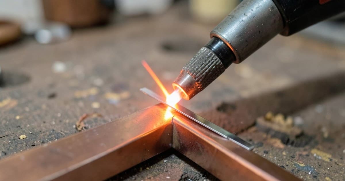
Learning how to weld thin metal is mostly learning how to manage heat. On thick plate, a hot arc is forgiving because the surrounding metal soaks up the excess. On sheet, there is almost nothing to absorb it, so the puddle either sags into a hole or the whole panel ripples like a potato chip.
The good news is that burn-through is rarely a talent problem. It is a predictable result of too much heat going into too little metal for too long, and every fix comes down to putting in less heat, spreading it out, or carrying it away faster. This guide walks through each lever in the order you will meet them at the bench: material and joint, process, settings, technique, distortion control, safety and troubleshooting.
Why Thin Metal Behaves Differently
Thin sheet has very little thermal mass. Heat from the arc cannot flow away quickly through the cross-section, so the weld pool grows fast, the base metal beside it softens, and surface tension alone is left holding molten metal in place. If the pool grows past what the sheet can support, gravity wins and you get a hole.
Two things go wrong at the same time:
- Burn-through: the pool melts completely through the joint and falls out, or the arc cuts a hole beside the joint.
- Distortion: the weld and the metal next to it expand, then shrink as they cool, and the unheated sheet resists. On thin material that resistance is low, so the panel buckles, bows or waves.
Technical guidance on distortion describes the same chain of events: locally heated metal expands, cools, and contracts, and the amount of resulting movement depends heavily on heat input and on how much restraint the part has. Those are the two variables you can actually control at the bench.
What counts as "thin"
There is no universal cutoff, and the label depends on the process and the material. As a working rule, once the sheet is thin enough that you can feel the panel heat up along its whole width during a single bead, you are in thin-metal territory. Automotive body panels, ductwork, enclosures, tubing walls and light brackets all fall here.
Different metals shift the picture:
- Mild and low-carbon steel conducts heat moderately and is the most forgiving.
- Stainless steel holds heat in the weld zone because it conducts poorly, so it distorts and discolours more easily.
- Aluminium conducts heat away very quickly, then suddenly collapses when the temperature rises past the point where the oxide skin and base metal give up. It often seems fine until it is not.
The Core Principle: Control Heat Input
Heat input is the energy delivered per unit length of weld. It rises with current and voltage and falls with faster travel speed. A weld that is too hot for thin sheet is almost always a combination of settings that are too high and travel that is too slow.
Many beginners respond to a hole by simply turning the machine down. That can help, but it can also cause a cold, ropey bead with poor fusion if travel speed does not change with it. The goal is not the lowest possible current; it is the lowest heat that still achieves fusion at a steady travel speed.
Takeaway: you control heat with three things at once: current and voltage, travel speed, and how much of the weld you do before letting the metal cool. Change them together, not one at a time.
Choose the Right Process for the Sheet
Several arc processes can join sheet, but they are not equally suitable. The two most common choices are MIG and TIG, and each has a place.
MIG welding thin metal
If you are new to the basics, what is migmag welding covers how the process works. For sheet, the important idea is the transfer mode. At low voltage and wire speed, short-circuit transfer delivers molten metal in small, repeated contacts between the wire and the pool. Because the arc keeps going out and re-igniting, average heat stays low, which is why short-circuit transfer is the usual choice for thin steel.
Practical points for MIG on sheet:
- Use a small-diameter wire. A thinner wire needs less current to melt, so it can run at lower settings.
- Keep the stickout consistent. A wandering stickout changes current on its own and causes sudden spikes in heat.
- Run a shielding gas suited to thin steel. Gas choice affects arc character and penetration, and richer argon mixes generally give a calmer, cooler-looking arc than pure CO2.
- Use a clean, dry joint. Contamination makes the arc unstable, and an unstable arc is an uneven heat source.
For starting settings by wire size, a wire-speed and voltage chart is the right reference, and mig welding wire speed voltage chart explains how to read one and adjust it for your machine. Treat any chart as a starting point and confirm on scrap of the same thickness.
TIG welding thin metal
TIG gives the finest heat control because current is adjusted independently from filler, and a foot pedal or torch control lets you ramp heat up and down during the weld. If you are comparing processes, what is tig welding lays out the fundamentals.
On thin sheet, TIG has several advantages:
- You can fuse edges without adding filler in some joints, which keeps the bead flat and low.
- A narrow, focused arc heats a smaller area than a MIG arc.
- Pulsed current alternates between a hot peak and a cooler background, so the puddle forms during the peak and partly freezes during the background. That reduces the average heat flowing into the part, and many modern machines include pulse for this reason.
- Weld appearance is cleaner, which matters on visible work.
The tradeoff is speed and skill. TIG is slower, and keeping a steady arc length with one hand while feeding filler with the other takes practice. For reference on how current relates to thickness, see tig welding amperage chart.
Other options
Resistance spot welding, brazing and adhesive bonding are all used on sheet, and each puts less heat into the panel than a continuous arc weld. Stick welding is a poor fit for very thin material because the arc is difficult to control at low current, though it can be workable on the upper end of the sheet range with small electrodes and a broken-arc technique.
Process comparison
| Factor | MIG (short-circuit) | TIG |
|---|---|---|
| Heat control | Good, tied to wire speed and voltage | Excellent, independent of filler |
| Speed | Fast | Slower |
| Skill needed | Moderate | Higher |
| Weld appearance | Acceptable, may need finishing | Very clean |
| Best for | Production, repairs, general fabrication | Visible joints, stainless, aluminium, precision work |
Fit-Up and Joint Design Decide Half the Outcome
Many holes are blamed on settings when the real culprit is fit-up. On thick plate a root gap helps penetration. On sheet it is a hole waiting to happen, because there is no extra metal at the edges to bridge a gap.
Keep the gap tight
Bring the edges into contact along the full length of the seam. Clamp the parts so they stay in place as heat is applied. If the gap varies along the joint, the arc will burn through at the widest spot while barely fusing the narrow ones.
Pick a joint that suits the material
Different joint types handle heat differently:
- Lap joints: the overlap doubles the metal thickness at the seam, so the arc is less likely to cut through. These are common in automotive and enclosure work.
- Flanged or edge joints: turning up an edge on both pieces gives a small amount of extra material to melt and creates built-in stiffness.
- Butt joints: they give a flush surface but are the least forgiving. They need a tight fit and careful heat control, often with backing.
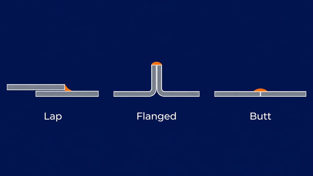
Figure 1: A lap joint doubles the metal at the seam, a flanged joint adds material to melt, and a butt joint needs the tightest fit.
Design choices that reduce weld length, reduce weld size or avoid welding on one side only will also reduce distortion. Guidance on distortion control through fabrication techniques consistently points to the same idea: use no more weld metal than the joint needs, because every extra bit of deposited metal adds shrinkage.
Clean the metal first
Remove oil, rust, mill scale, paint and coatings from the joint area. Dirt and coatings disturb the arc and cause porosity, and an erratic arc is a hard one to hold at low heat. Clean the back of the joint too if it sits against a backing bar or will be visible.
Setting Up the Machine
Settings depend on the machine, material, joint and wire or electrode, so use these as principles rather than numbers.
Start low and work up
Begin at the low end of the range for the thickness and make a test bead on a scrap piece of the same material. If it fails to fuse, increase heat in small steps. If the arc is already close to cutting through, the next change should usually be faster travel rather than lower current.
Match current, voltage and travel
For MIG, voltage sets arc length and bead shape while wire speed sets current. Too low a voltage causes stubbing and a pile-up of wire; too high makes a long, hot arc that wanders. Adjust the two together until the arc sounds steady and consistent.
For TIG, keep the tungsten sharp and the arc short. A long arc spreads heat over a wider area and is hard to direct. Ramp the current down at the end of the bead to avoid a crater and a pinhole at the finish.
Pulse and low-heat modes
Many inverter machines offer pulsed MIG or TIG, or controlled short-circuit modes designed for sheet. They reduce average heat by shaping the waveform. They are useful, but they do not replace good fit-up and sequencing. A pulse setting on a poor joint still burns through.
Gas coverage
Poor shielding adds porosity and spatter. Use a flow rate suited to the nozzle and conditions, and shield the work from draughts. On stainless, protection of the back of the weld may be needed to avoid oxidised, sugary root surfaces.
Technique That Keeps the Pool Under Control
Once the machine is set up, the details of how you move matter more than most people expect.
Stitch, do not run
Rather than one continuous bead, lay short welds, pause so the metal can cool, then continue. Short segments keep the heat from building up in one area. Let the part lose its glow or colour before overlapping the end of the previous segment.
Tack in the right order
Tack welds hold the fit-up in place and also control movement:
- Place the first tack in the middle of the seam.
- Place tacks at each end.
- Fill in the middle of each remaining gap, halving the spacing each time.
Tacking steadily from one end to the other pushes shrinkage toward the far end and often leaves the panel bowed.
Use sequencing to balance the heat
Welding sequences distribute the shrinkage so it cancels out rather than accumulates:
- Skip welding: make a short weld, jump a distance along the seam, weld again, then return to fill the gaps.
- Backstep welding: weld short segments against the overall direction of travel so each piece of shrinkage opposes the last.
- Alternate sides: on parts with welds on both sides, alternate between them so the pull from one is balanced by the other.
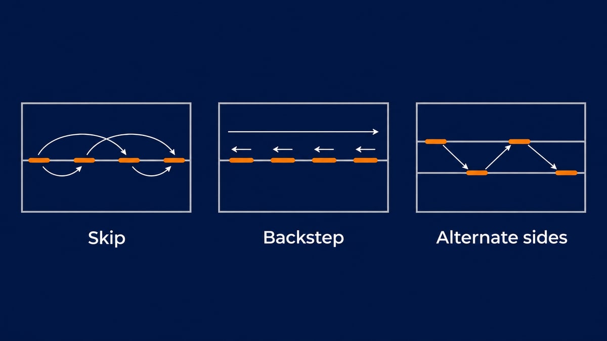
Figure 2: Short segments placed out of order, or against the direction of travel, spread the shrinkage instead of stacking it in one place.
Guidance on distortion repeatedly notes that welding all of one side first creates more distortion than alternating, because the shrinkage is one-sided.
Mind the torch angle and travel
Keep the travel speed steady and brisk. A gun held too steeply in a drag position drives the arc deeper and concentrates heat in one spot, which is a common cause of holes on very thin material. A modest push angle gives a shallower profile and a cleaner face. Avoid weaving widely on sheet; a wide weave spreads heat across more of the part.
Point the arc at the thicker part
If the two parts differ in thickness, such as sheet to angle or sheet to tube, aim the arc toward the heavier piece and let the puddle wash onto the thin one. The heavier side absorbs more heat and prevents the thin edge from melting away.
Do not stop and linger at the end
Leaving the arc in one place at the end of a bead is where many holes appear, because the sheet is already hot. Finish with a controlled taper or lift out smoothly, and let the area cool before moving on.
Backing Bars and Heat Sinks
One of the most effective ways to prevent burn-through is to give the heat somewhere to go.
Copper or aluminium backing
A copper bar clamped behind the seam conducts heat away quickly and does not fuse to steel, so it supports the puddle and then comes away after welding. It is a standard technique for butt joints in sheet. Grooved backing bars can also shape the root bead and hold shielding gas on the back side for stainless work.
Heat sinks beside the weld
Chill bars or clamps placed close to the weld on either side draw heat out of the area. Wet rags are sometimes suggested, but they can introduce moisture and cause cracking or hardening in some steels, so use them with caution or choose metallic heat sinks instead.
Fixtures and restraint
Clamping the panel to a rigid table or fixture limits movement while the metal is hot. Restraint can reduce visible distortion but increases residual stress in the part, so release clamps only after the metal has cooled. On parts with tight tolerances, check the shape after release.
Preventing and Correcting Distortion
Distortion is often the more stubborn problem on sheet, even when you avoid burning through.
Reduce heat and weld volume
- Use the smallest weld size that meets the requirement.
- Use intermittent welds where the design allows them instead of continuous ones.
- Keep the arc short and the travel steady.
Pre-set and pre-bend
If you know a joint will pull in a certain direction, set the parts slightly in the opposite direction before welding so shrinkage pulls them into position. This is standard practice in fabrication, and TWI job-knowledge material on distortion control lists pre-setting alongside balancing welds and using restraint.
Plan the order of assembly
Weld sub-assemblies where shrinkage has freedom to move, then join them into the larger structure. Fully restrained, late-stage welds tend to leave locked-in stress and unpredictable movement.
Straightening afterwards
Minor waves can sometimes be removed with controlled local heating and cooling or mechanical planishing, but both can damage thin material and change its properties. Treat straightening as a repair of last resort and test on offcuts first.
A Hypothetical Walk-Through
The following example is hypothetical and is meant to show how the principles combine.
Imagine two flat steel sheets that need to be joined into a long seam for an enclosure. The first attempt runs one continuous MIG bead from end to end with a small root gap. The panel bows upward and a hole opens in the middle where the gap was widest.
On the second attempt:
- The edges are clamped tight with no visible gap.
- Tacks go in middle-first, then ends, then the middle of each gap.
- A copper backing bar supports the seam.
- The seam is welded in short stitches using a skip sequence, with a pause between each.
- The clamps stay on until the panel has cooled.
The result is a flatter panel and no holes. The settings might have barely changed. Fit-up, sequencing and cooling did the work.
Metal-Specific Notes
Mild and low-carbon steel
This is the easiest material to practise on. Short-circuit MIG with a thin wire and small stitches is usually enough. Watch for mill scale, which can interrupt the arc.
Stainless steel
Stainless holds heat and distorts more readily, so keep heat input low and sequences short. It also oxidises on the back of the weld if not protected, so backing gas or a grooved backing bar can protect the root. Overheating shows up as heavy discolouration.
Aluminium
Aluminium needs more care. It conducts heat quickly but has a low melting point and shows little colour change as it approaches collapse, so it can go from solid to a hole with little warning. TIG with AC and good cleaning is usual. Clean the oxide layer just before welding, and use a heat sink to avoid sudden collapse.
Galvanized and coated sheet
Zinc coatings burn off at the weld and can cause porosity. They also create hazardous fume, discussed next, so remove the coating at the joint where possible and ventilate well.
Safety Considerations
Thin-sheet work is often done on coated, painted or galvanized material, which brings specific hazards.
- Galvanized steel: welding galvanized or zinc-coated steel produces zinc oxide fume. Overexposure can cause metal fume fever, a short-lived flu-like illness. OSHA and medical references both identify zinc fume from galvanized material as a common cause.
- Stainless steel: fume can contain chromium compounds, so local exhaust or respiratory protection is appropriate under the rules that apply to your workplace.
- Paint, oil and plastics: heat can release toxic decomposition products. Remove coatings and residues from the weld zone before striking an arc.
- Spatter and sparks: sheet is often welded close to flammable materials such as upholstery and wiring in vehicle work. Clear the area and keep fire protection nearby.
General safety guidance from OSHA stresses controlling fume and gases through ventilation and, when needed, respiratory protection. Follow your local regulations and the manufacturer's safety data for consumables and coatings, and keep the baseline protections for every job in place. This article is general information and not a substitute for a workplace hazard assessment.
Troubleshooting Common Problems
Holes and burn-through
Likely causes: settings too high, travel too slow, gap too wide, or lingering at the end of a bead. Fixes: increase travel speed, reduce current or wire speed, close up the gap, add a backing bar and stitch the weld.
Warping and waves
Likely causes: too much heat input, continuous welds, one-sided welding or insufficient restraint. Fixes: shorten the welds, balance them across the part, clamp during cooling and consider pre-setting.
Cold lap and poor fusion
Likely causes: settings too low or travel too fast after over-correcting for burn-through. Fixes: increase heat slightly and confirm fusion by cutting or bending a test piece.
Porosity
Likely causes: contamination, coatings, gas shortage or draughts. Fixes: clean the metal, check gas flow and shield from wind.
Undercut
Likely causes: excessive voltage, too fast a travel or poor torch angle, which cut a groove beside the bead. Fixes: reduce voltage slightly and keep the arc centred on the joint.
Spatter and a rough arc
Likely causes: wrong voltage and wire speed combination, dirty wire or a worn contact tip. Fixes: re-tune settings and replace consumables.
Common Mistakes to Avoid
- Practising on the actual part instead of a test piece of the same thickness and grade.
- Leaving a root gap on sheet.
- Welding a continuous bead because it seems faster.
- Tacking from one end to the other.
- Using too large a wire or electrode for the material.
- Releasing clamps while the part is still hot.
- Assuming the same settings will work on stainless and aluminium as on mild steel.
Quick Checklist Before You Strike an Arc
- Metal clean and coatings removed at the joint
- Edges tight, clamped and supported
- Backing bar or heat sink in place where useful
- Wire or tungsten size matched to thickness
- Test bead made on scrap of the same material
- Tack order and stitch sequence planned
- Ventilation and fire precautions in place
Putting It All Together
Welding sheet successfully means treating heat as a budget. Choose the process that gives you the control you need, bring the edges together properly, start with conservative settings, and break the weld into short, balanced stitches with time to cool. Add a backing bar when the joint is unforgiving and keep clamps on until the metal has relaxed.
Practise on scrap until you can predict how the metal will react. Once the fit-up, sequence and travel speed become habits, burn-through stops being a surprise and starts being something you can see coming and avoid.
Frequently asked questions
What is the best welding process for thin metal?
TIG gives the finest heat control and the cleanest appearance, especially on stainless steel and aluminium. Short-circuit MIG with a thin wire is faster and works well on mild steel for repairs and production. The best choice depends on appearance requirements, material and your skill level.
Why does my weld keep burning through thin sheet?
The most common causes are too much heat for the thickness, slow travel speed and a gap between the parts. Tight fit-up, faster travel, lower current and short stitches with cooling pauses usually solve it. A backing bar helps when the joint is still unforgiving.
What amperage should I use for thin metal?
It depends on the material, thickness, process and electrode or wire size, so there is no single correct number. Start at the low end of a chart for your thickness, then test on scrap of the same material and adjust in small steps. A chart is a starting point, not a guarantee.
How do I stop thin sheet from warping?
Reduce heat input, use short intermittent welds, balance the welds across the part, and clamp the sheet to something rigid while it cools. Pre-setting the parts slightly against the expected pull can also help. Straightening afterwards is harder than preventing the distortion.
Can I weld thin metal with a stick welder?
It is possible on the thicker end of the sheet range with a small electrode and a broken-arc technique, but it is difficult to control and often leaves a rougher result. For most sheet work, MIG or TIG is easier and more predictable.
Is a copper backing bar worth using?
Yes, on butt joints and any seam where the pool tends to fall through. Copper pulls heat out of the joint and supports the puddle without fusing to steel. It is one of the simplest ways to improve results on thin sheet.
Should I use pulse settings on thin metal?
Pulse can lower average heat by alternating between a high peak and a lower background current, which helps on sheet. It does not replace good fit-up and sequencing, so use it together with them rather than as a fix on its own.
Does thin aluminium need different techniques from steel?
Yes. Aluminium conducts heat away quickly but collapses with little visible warning, and it needs its oxide layer cleaned just before welding. TIG with AC is common, and heat sinks and careful travel help avoid sudden holes.
Is it safe to weld galvanized sheet?
It can be done, but the zinc coating releases fume that can cause metal fume fever and other health effects. Remove the coating at the joint where practical, ventilate or use extraction, and use respiratory protection where required by workplace rules.
Why does thin stainless steel discolour so much?
Stainless conducts heat poorly, so heat stays in the weld zone and oxidises the surface, especially on the back side. Lower heat input, shorter stitches and protection of the root with backing gas or a grooved backing bar reduce the discolouration.
How can I practise welding thin metal?
Use offcuts of the same material and thickness as the real job, and run test beads while changing one variable at a time. Practise tacking in the middle-first order and skip sequences, then cut or bend the test pieces to check fusion.
References
- Distortion - Types and Causes - TWI Ltd. Explains how heat input and restraint influence welding distortion.
- Distortion Control - Prevention by Fabrication Techniques - TWI Ltd. Covers procedure and fabrication measures that limit distortion.
- Welding, Cutting, and Brazing - Overview - Occupational Safety and Health Administration, accessed 2026-11-16.
- Controlling Hazardous Fume and Gases during Welding - Occupational Safety and Health Administration, 2013. Fact Sheet 3647 on fume and gas control.
- Metal Fume Fever - StatPearls, NCBI Bookshelf, 2023. Clinical overview of fume exposure from zinc-coated material.