
Welding Symbols Explained
Welding symbols chart and reading guide: reference line, arrow side vs other side, fillet and groove symbols, size callouts and AWS vs ISO 2553 differences.

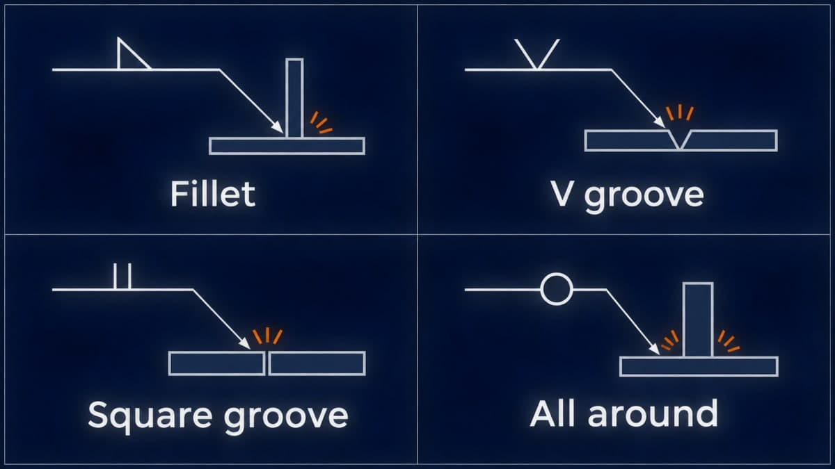
A welding symbols chart looks like a wall of tiny triangles, circles and flags until you learn the one rule behind it: every symbol is a short instruction written around a single line. Once you know where the line, the arrow and the tail sit, the rest is reading left to right and top to bottom. This guide walks through the anatomy of a welding symbol, the basic weld shapes, the supplementary marks, and the place where the two main systems, AWS and ISO 2553, can mislead you.
The goal is practical. By the end you should be able to look at a drawing, say which side of the joint gets welded, what type of weld goes there, and what extra information the designer packed into the symbol. You should also know when to stop guessing and ask.
Why welding symbols exist
A drawing shows the geometry of a part. It does not say how the pieces are joined. Welding symbols add that missing layer in a compact form, so a designer can tell a fabricator where to weld, what kind of weld to make, how big it should be, and any special finishing or process notes.
Without a shared symbol language, every shop would need written notes on every joint. With one, a single mark carries the same meaning from the engineer's desk to the welding bay. That only works if both sides read the symbol the same way, which is why the standard in use matters as much as the symbol itself.
If you are building toward a qualification, reading symbols is part of the everyday skill set that employers expect. The path described in how to become a certified welder assumes you can already interpret a drawing without help.
The anatomy of a welding symbol
The complete welding symbol has a few fixed parts. Learn these and the rest of the chart falls into place.
- Reference line: the horizontal line that carries almost all the information.
- Arrow: the line from the reference line to the joint. It tells you which joint the instruction applies to.
- Tail: an optional fork at the far end of the reference line. It holds notes such as the welding process, a procedure reference or a filler requirement.
- Weld symbol: the shape (triangle, V, square and so on) placed on the reference line.
- Dimensions: numbers placed beside the weld symbol.
- Supplementary symbols: circles, flags and contour marks that modify the basic weld.
Figure 1 shows how these parts sit together on a simple tee joint.
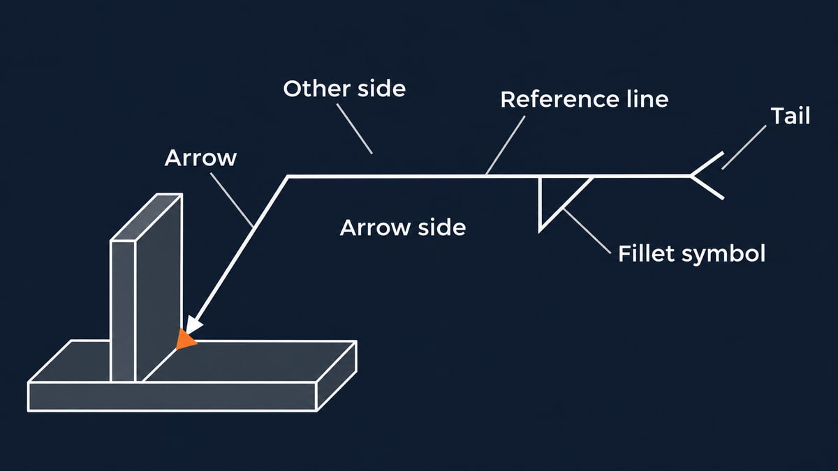
Figure 1: The arrow points at the joint, the reference line carries the weld symbol, and the tail holds notes.
A practical detail that trips up beginners: the tail is optional. If there is nothing to say about process or procedure, the tail is simply left off. A missing tail does not mean missing information; it means no extra note was needed.
Arrow side and other side
This is the single most important concept in the whole system. The reference line has two sides, and the side where the weld symbol sits tells you which face of the joint gets welded.
In the AWS system, which uses one continuous reference line:
- A symbol below the reference line means the weld goes on the arrow side of the joint.
- A symbol above the reference line means the weld goes on the other side.
- Symbols on both sides mean the joint is welded from both sides.
"Arrow side" and "other side" are defined relative to the joint the arrow touches, not relative to where you are standing. Arrow side is the face of the joint the arrow points to. The other side is the opposite face. People often read them as "near" and "far", and that shortcut can put a weld on the wrong face of the plate.
Check before you strike an arc: find the joint the arrow touches, then decide which member the arrow points at. Only then look at whether the symbol is above or below the line.
The basic weld symbols
The shape on the reference line tells you the type of weld. Most work uses a small family of shapes.
Fillet weld
A fillet weld sits in the corner where two surfaces meet at an angle, as in a tee joint or a lap joint. The symbol is a right triangle. The vertical side of the triangle is always drawn on the left, regardless of which side of the line it is on.
The fillet is by far the most common symbol on structural and general fabrication drawings, so it is the one worth memorizing first.
Groove welds
Groove welds fill a prepared gap between two members, usually in butt joints. The symbol shape mirrors the edge preparation:
- Square groove: two short parallel lines; edges left square, usually with a small root gap.
- V groove: both edges beveled to form a V.
- Bevel groove: one edge beveled, the other left square. The arrow is bent toward the beveled member.
- U groove: both edges machined with a curved root, common on thicker material.
- J groove: one edge machined to a curved root, the other left square.
For bevel and J grooves, the broken arrow points at the member that receives the preparation. That small bend is easy to miss and it matters.
Plug, slot, spot and seam
- Plug and slot welds fuse one plate to the one behind it through a round or elongated hole.
- Spot and projection welds are resistance welds made at a point between overlapping sheets.
- Seam welds are continuous resistance welds along a line.
These appear mostly in sheet metal and thin-gauge assemblies. For structural and pipe work, fillets and grooves cover most of what you will meet.
Back and backing welds
A back weld is run on the root side of a groove weld after the groove is made. A backing weld is made first, to form a base for the groove weld. Both are drawn opposite the groove symbol on the reference line.
Reading size, length and pitch
Numbers on the reference line carry the dimensions. Their position is fixed by convention, which makes them readable once you know the pattern.
- Fillet size sits to the left of the triangle. A single number usually means equal legs.
- Length sits to the right of the symbol.
- Pitch (center-to-center spacing for intermittent welds) follows the length after a dash.
Groove depth and root opening follow a similar logic: the depth of preparation is placed to the left of the symbol, and the root opening is shown inside the symbol. For complete penetration, check how the drawing notes it rather than assuming.
A worked reading, described in words: a triangle on the lower side of the line, with a number to its left and a length and pitch to its right, means an intermittent fillet weld on the arrow side, of the stated size, in segments of the stated length, spaced at the stated pitch. If the drawing gives a single number only, the fillet is continuous for the length of the joint unless the drawing says otherwise.
Dimension units follow the drawing. Do not mix inches and millimeters inside one symbol, and confirm the unit in the title block if the sheet is ambiguous.
Supplementary symbols
Supplementary symbols modify a basic weld instead of replacing it. A short list covers most of what you will see:
- Weld all around: a circle where the arrow meets the reference line. The weld continues around the whole joint, such as a pipe or a rectangular frame.
- Field weld: a flag at the same point. The weld is made on site rather than in the shop.
- Melt-through: a filled semicircle opposite the groove symbol. The weld is made from one side so it fully penetrates and leaves a bead on the back.
- Contour marks: a flat line (flush), a curve bulging out (convex) or a curve dipping in (concave) tells you how the finished weld face should look. A finishing letter near the contour mark, such as a grinding or machining code, says how to get there.
Contour marks are often misread as decoration. They are instructions about the surface, and they can mean extra work after welding.
Where the tail comes in
The tail holds notes that do not fit anywhere else. Typical entries are the welding process, a reference to a written procedure, electrode or filler requirements, or an inspection note.
If the tail names a procedure, the real working detail lives in that document, not on the drawing. For how to read that document once you have found it, see how to read a wps. The symbol points to the procedure; the procedure sets the parameters.
AWS and ISO 2553: the same line, a different rule
This is the part that causes real expensive mistakes. The two systems share the reference line concept, but they define the sides differently.
| Feature | AWS A2.4 (and ISO 2553 B-system) | ISO 2553 A-system |
|---|---|---|
| Reference line | One continuous line | Continuous line plus a dashed line |
| Arrow side | Symbol below the line | Symbol on the continuous line |
| Other side | Symbol above the line | Symbol on the dashed line |
| Symmetrical welds | Symbols on both sides | Dashed line omitted |
The trap is that ISO's A-system lets the dashed line be drawn above or below the continuous line, and a preference is stated for drawing it below. That is exactly where AWS says arrow side. A welder trained on one system and reading a drawing from the other can weld the wrong face of the joint without noticing.
Two habits protect you:
- Identify the system first. Check the title block and the standard noted on the sheet. If there is a dashed line next to the reference line, it is the A-system.
- Do not identify the system from a single symbol. A symmetrical double fillet in the A-system has no dashed line and looks identical to an AWS symbol.
The difference between the two bodies is not only about drawings. It runs through qualification too, as covered in aws vs iso 9606, so anyone working across markets benefits from knowing both conventions.
A practical reading routine
Use the same order every time. It keeps you from jumping to the shape and missing the rest.
- Confirm the standard in the title block.
- Find the arrow and the joint it touches.
- Decide the side: arrow side or other side, using the rule for that system.
- Identify the weld shape on the reference line.
- Read the dimensions around it: size on the left, length and pitch on the right.
- Check for supplementary marks: all-around, field, contour, melt-through.
- Read the tail for process, procedure and notes.
Figure 2 compares the same joint drawn with the symbol on each side of the line, which is the quickest way to see why step 3 matters.
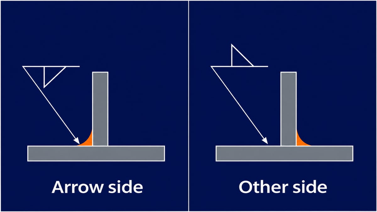
Figure 2: Same symbol, same joint: below the line puts the weld on the arrow side, above the line puts it on the other side.
Common mistakes
- Reading near and far instead of arrow side and other side. The sides belong to the joint, not to the reader.
- Ignoring the tail. A procedure reference or process note can change how the weld is made.
- Treating size as optional. A fillet with no size is not a license to choose; check the general notes on the drawing.
- Mixing up AWS and ISO. The dashed-line rule is the most common source of wrong-face welds.
- Skipping the finishing mark. A flush or convex symbol may require grinding after the weld.
- Assuming a chart replaces the standard. A chart is a reading aid.
What a chart cannot do
A welding symbols chart is a reading aid, not an authority. Simplified drawings leave out details, and the controlling document is the applicable standard and the project drawing set. If a symbol is ambiguous, or the drawing and the chart seem to disagree, ask the designer or the responsible engineer before welding. Redoing a weld on the wrong face costs far more than a short question.
Conclusion
Welding symbols stop being intimidating once you read them in a fixed order: standard, arrow, side, shape, dimensions, supplementary marks, tail. The two ideas to carry away are that the side rule belongs to the joint the arrow touches, and that AWS and ISO 2553 do not always agree about what "below the line" means. Keep a reliable chart nearby while you learn, verify it against the standard the project uses, and ask whenever a drawing is unclear.
Frequently asked questions
What do the three parts of a welding symbol mean?
The reference line carries the weld information, the arrow points to the joint, and the optional tail holds notes such as the process or a procedure reference.
What is the difference between arrow side and other side?
Arrow side is the face of the joint that the arrow points to. Other side is the opposite face of the same joint. They are defined by the joint, not by where the reader stands.
How do I know which side a weld goes on?
In the AWS system, a symbol below the reference line means arrow side and a symbol above the line means other side. Symbols on both sides mean the joint is welded from both sides.
What does the triangle symbol mean on a welding drawing?
A right triangle is the fillet weld symbol. It describes a weld in the corner of a tee, lap or corner joint, and its vertical side is always drawn on the left.
Where is the weld size written?
For fillet welds the size is placed to the left of the triangle. Length and pitch for intermittent welds go to the right of the symbol.
What does a circle at the arrow joint mean?
A circle where the arrow meets the reference line means weld all around: the weld continues around the whole joint, such as a pipe or a frame.
What does a flag on a welding symbol mean?
A flag at the arrow junction marks a field weld, meaning the weld is made on site rather than in the shop.
Are AWS and ISO welding symbols the same?
No. Both use a reference line and an arrow, but they differ in how the sides are shown. The ISO 2553 A-system uses a continuous and a dashed line, while the AWS system and ISO B-system use a single line with above and below positions.
How can I tell which system a drawing uses?
Check the title block for the standard, and look for a dashed line beside the reference line. A dashed line indicates the ISO A-system. A single symmetrical symbol alone cannot identify the system.
Where do I find the welding process on a symbol?
The process or procedure reference is usually written in the tail. The actual parameters sit in the referenced procedure document.
What should I do if a welding symbol is unclear?
Stop and ask the designer or responsible engineer. Check the standard named on the drawing, not just a chart, before welding.
References
- Fillet weld - Wikipedia, accessed 2026-11-18. Parts of a fillet weld, reference line, A-system and B-system conventions, size placement and contour symbols.
- Welding joint - Wikipedia, accessed 2026-11-18. The five joint types referred to by the American Welding Society and butt joint geometries.
- MER419 Lecture 13: Welding Introduction - Union College, accessed 2026-11-18. University lecture material on weld types and symbols.
- Print Reading: Welding Design - Illinois State Board of Education, accessed 2026-11-18. Reference line, arrow and tail as the three main parts of a welding symbol.
- Welding Drawings, Chapter 22 - De Anza College, accessed 2026-11-18. Fillet size shown on the same side of the reference line, to the left of the weld symbol.
- Welding symbols chart: AWS and ISO weld symbols explained - Fabora, accessed 2026-11-18. Supplier source: used only for the AWS and ISO side-convention comparison, which should be checked against the standards themselves.